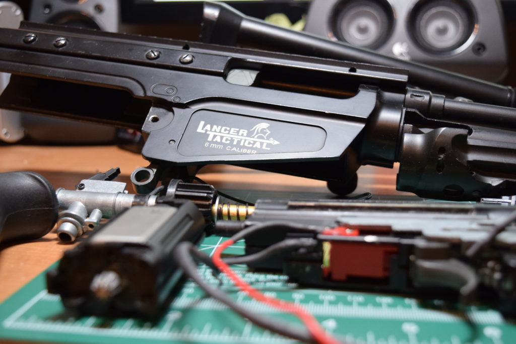
A friend of mine had an old FAL AS-58 by Lancer Tactical which he had been having electrical issues. He had it torn down and did not have the electrical experience to figure out the issues, he switched to a gas blow back M4 last year and it has been sitting in his closet since. Recently, he gave the parts to me to see if I can get some use out of it.
First step, figure out what I have, are all of the parts together.
I took each part and figured out where it goes, since it was provided in pieces, I dry-fit everything together piece by piece to figure out which piece goes where.
Unfortunately, I did not have a manual or exploded diagram of the AEG and after attempting to contact Lancer Tactical, they did not respond. Even their website has no support information for this replica, or really any data whatsoever, FAL-AS-58 link here.
With the lack of documentation available, best guess it is!
Most of the pieces were easy, how to get the motor grip on to the main body with the gear box, how to attach that to the upper receiver etc is fairly self explanatory. The first real pain point came with the barrel and hopup chamber fitment.
Now, fair warning, the most tech work I’ve done with my own weapons is field stripping and cleaning my KWA HK45, Tippmann M4, and replacing the motor on my JG W4-System M4. This was new territory for me so I dove in using the great Google as much as I could to research the hopup. One problem I had was what pieces actually made up the unit. There is the full metal hopup chamber, obviously, the bucking and nub, those are standard, but what about the plastic wheel, spring and washer ? How do those fit together.
With a little searching, I found a FAL hopup replacement on Evike which shows all of the parts that are used with the hopup assembly, that reduced the mystery.
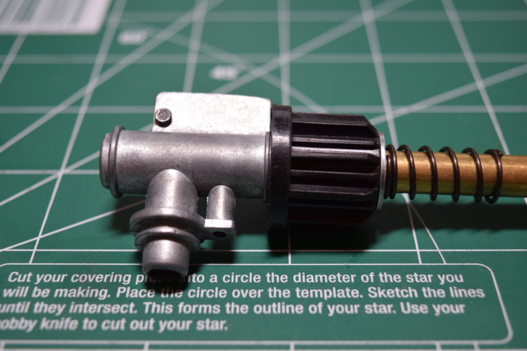
First, I’ll show the finished product:
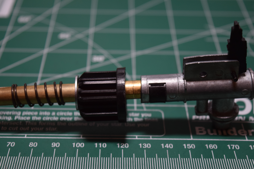
Here is a shot with the pieces slightly separated to show the order they go in.
What are the pieces seen above ? In order from left to right they are;
- Tension Spring – puts back pressure between the upper receiver and hopup unit and plunger nozzel.
- Washer – used as a spacer between the spring and the hopup adjustment knob
- Hopup Adjustment Knob – The back of this is grooved, slot the hopup lever into this when putting it together.
- Hopup Unit – The full metal hopup is a big piece that envelopes the portion of the barrel that has the hopup bucking and nub.
- Clip – The black clip has a right and wrong way that is based on notches to help hold everything together.
- Hopup Lever – (sticking up), is used to put pressure onto the hopup nub (unseen)
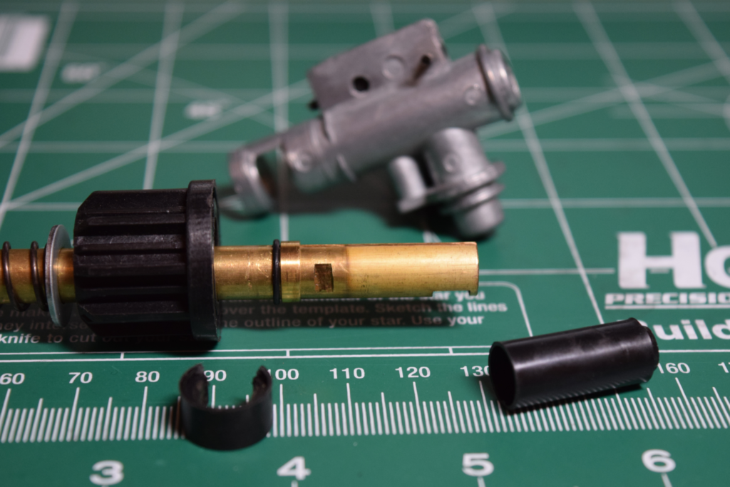
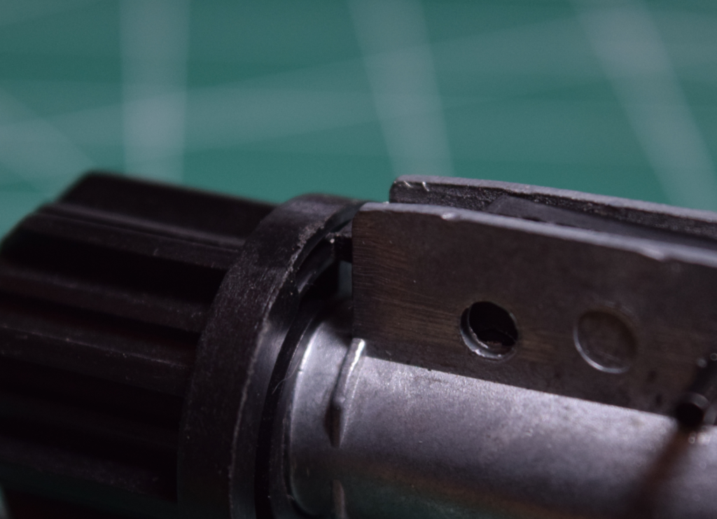
And, a final shot that shows nearly all of the pieces removed, except the o-ring and collar next to it that are still on the barrel.
When assembling the hopup with the barrel and the hopup control lever, it is important that you fit the notch of the lever into the groove of the adjustment knob. I prefer to seat the nob at the very highest setting (least hopup) to start with.
Once the hopup and barrel are fitted together, they slide into the upper receiver with the bb entry stem pointed downwards and through the outer-barrel assembly.
Now that I’ve figured out what goes where, it is time to figure out what went wrong in the next post.
